Custom Thermoformed Trays for Aerospace and Defense Manufacturing
In aerospace and defense manufacturing, a tray is rarely just packaging. It may establish part orientation at an assembly cell, separate critical surfaces during inspection, present components to a robot, control kit quantity, or move sensitive hardware between suppliers and production sites.
That tray becomes a problem when it is treated as an afterthought. Loose parts shift in oversized totes. Temporary inserts add loose material or hide debris. Operators rotate components by hand because cavities do not match the next operation. Trays stack in storage but become unstable when loaded. Electronics leave an electrostatic protected area in packaging that was only specified as “anti-static.”
A custom thermoformed tray can remove those variables by giving each part a defined location, orientation, and contact pattern. The design still has to account for the entire handling process—not only the shape of the component.
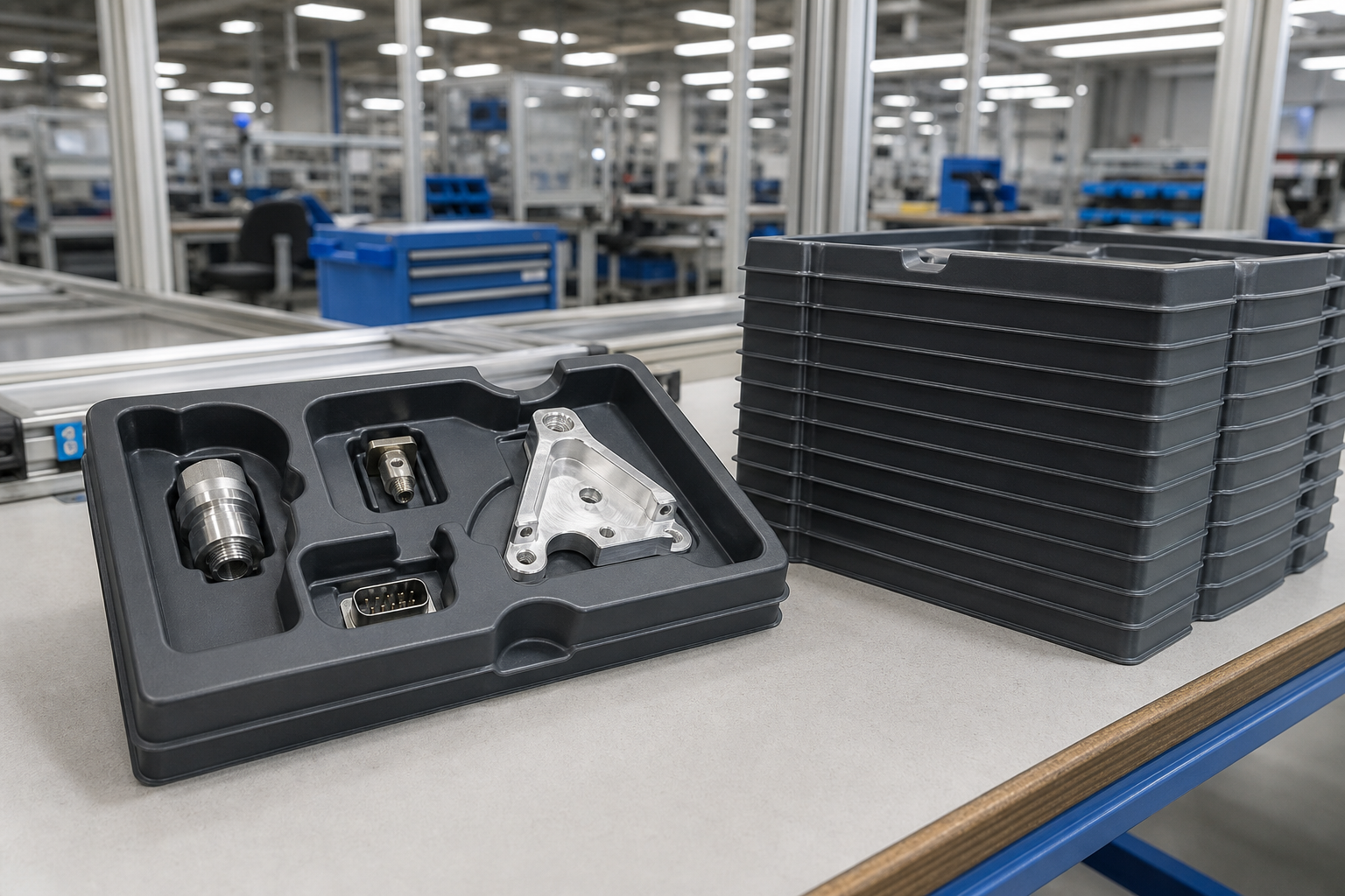
The Production Problems an Aerospace Tray Needs to Solve
Aerospace and defense components can move through receiving, machining, cleaning, inspection, subassembly, testing, storage, and final shipment. A tray that works at one station may create difficulty at another.
Common failures include:
- Parts touching each other or contacting a critical machined, coated, optical, or cosmetic surface.
- Components arriving in inconsistent orientations, adding manual handling before the next operation.
- Cavities that grip too tightly, release too easily, or give operators no practical finger clearance.
- Trays that fit the part but not the existing tote, rack, cart, conveyor, or returnable-packaging loop.
- Loaded stacks that transfer weight into the parts instead of through structural tray features.
- Empty trays that consume excessive floor and return-shipping space because they do not nest.
- Loose bags, foam pieces, dividers, or labels that add material and complicate visual checks for debris.
- Unclear electrostatic-discharge requirements for trays carrying electronic assemblies or devices.
These are process-control problems. Solving them starts with the part, the production sequence, and the customer's requirements before material or tooling is selected.
Where Custom Trays Fit in Aerospace and Defense Operations
Custom trays show up at several points in the production system. The cavity geometry may stay similar, but the handling requirement at each station is different. For related packaging capabilities, see our custom parts packaging service.
Work-in-process and assembly trays
WIP trays keep parts separated and consistently oriented as they move between operations. A fixed cavity count can also make shortages, overages, and incomplete kits easier to identify without unpacking a mixed container. For assembly work, cavity spacing, presentation angle, and hand clearance should reflect the actual loading and unloading motion. A tray that protects a component but slows every operator cycle is not fully designed for production.
Inspection and presentation trays
Inspection trays can expose the surfaces or features that quality personnel need to see while controlling contact elsewhere. The design may need access for gauges, scanners, vision systems, or part identification. The objective is not always maximum enclosure. In some cases, better presentation and simpler visual inspection are more valuable than a deep, tightly fitted pocket.
Kitting and multi-part trays
A dedicated cavity for each component can support sequence-of-use kitting and visual inventory control. Different cavity shapes can make a missing or misplaced part more apparent, while a defined layout can reduce sorting at the point of use. Combining too many part numbers into one design can reduce packaging variety, but it may also create unused cavities, awkward loading, or a tray that becomes obsolete after one component revision.
Robotic and automated handling trays
Automation depends on repeatable part location. Cavity pitch, tray datums, edge geometry, orientation features, and part release all affect whether a tray can serve as a reliable interface for pick-and-place equipment. The tray should be designed around the complete automated sequence: how it enters the cell, how it is located, how parts are detected and removed, and how the empty tray exits or nests. Consistent cavities alone do not guarantee automation compatibility.
Reusable inter-facility and supplier trays
Returnable trays may cycle among suppliers, machining operations, assembly plants, and distribution points. They need to protect the part while fitting the established tote or container system and remaining practical to store when empty. Expected reuse should be stated as a design requirement, not assumed from resin name or thickness. Handling severity, unsupported spans, cleaning, temperature, chemical exposure, and stack load can all influence useful life.
Designing the Tray Around the Part and the Process
Control contact at the right surfaces
The designer needs to know which surfaces may support the part and which must remain untouched. Critical no-contact areas may include sealing surfaces, precision edges, connectors, optical faces, coatings, threads, and Class-A finishes.
The cavity should restrain the component without creating concentrated loads or making removal difficult. Part weight and center of gravity matter, especially when a tray is accelerated on a conveyor, carried at an angle, or transported between facilities.
Choose orientation and cavity count deliberately
Consistent orientation can reduce rehandling and support faster loading at the next station. It may also improve error proofing when a component can only be placed in the correct direction.
Cavity count affects more than tray capacity. It changes tray size, loaded weight, operator reach, stack load, line-side inventory, and how quantities map to production batches. The highest cavity count is not automatically the most efficient design.
Design finger and robotic access separately
An operator may need finger scallops, lift clearance, or space for gloves. A robot may need a clear gripper path, known pickup height, visual access, or enough pocket relief to prevent vacuum or mechanical drag during removal.
If both manual and automated handling are expected, test both. A feature that helps one method can interfere with the other.
Treat stacking and nesting as different requirements
Loaded stacking should transfer compressive force through planned tray features rather than through the parts. Stack stops, rims, and load paths must be evaluated with the expected stack height and component weight.
Empty nesting reduces storage and return volume, but deep nesting can make trays difficult to separate. Designs may use controlled offsets, de-nesting features, or rotation to distinguish between the loaded-stack and empty-nest conditions.
Design to the existing material-handling system
Before defining the outside dimensions, document the tote, rack, shelf, cart, conveyor, pallet, and shipping-container interfaces. Allowance may be needed for labels, covers, bagging, cushioning, or manual access.
A tray designed without these constraints can fit the component perfectly and still fail at the plant. Manufacturers adding or transferring lines in the Midwest can also review our guide to thermoformed trays for Michigan manufacturers.
ESD Requirements Need More Precision Than “Anti-Static”
For electronic assemblies and electrostatic-discharge-sensitive items, conductive, static-dissipative, low-charging, and discharge-shielding are not interchangeable terms.
The correct packaging approach depends on the item, the customer's ESD-control plan, and where the tray will travel. Within an electrostatic protected area, packaging and handling materials generally need appropriate low-charging contact surfaces and conductive or dissipative characteristics that support the required grounding approach. When an item travels outside that protected area, discharge shielding may also be required.
Resistance categories by themselves do not prove that a finished tray is suitable for a particular device. The specification should identify the required property, test method, environmental conditions, grounding path, and any documentation or lot controls. Related handling considerations for electronic modules also appear in our article on thermoformed battery trays in production environments.
Before requesting an ESD tray, answer these questions:
- What component or assembly is being protected?
- Will the tray remain inside an electrostatic protected area?
- Must the loaded package travel outside that area?
- Is a conductive, dissipative, low-charging, or shielding function required?
- Does the customer specification identify a resistance range and test method?
- Are material certifications or finished-tray test results required?
How Tray Design Can Support FOD Risk Reduction
Foreign object damage prevention is a program-level responsibility, not a feature that a tray can guarantee. A well-designed tray can, however, support FOD-control objectives.
Dedicated cavities positively locate parts and make unexpected objects easier to notice. Smooth, accessible geometry can simplify visual inspection and cleaning. Replacing unnecessary loose foam, bags, dividers, or temporary inserts may reduce the number of packaging components in the work area.
The defensible objective is to reduce FOD exposure and support the customer's prevention process. Terms such as “FOD-free” or “FOD-proof” should not be used without a defined and validated basis covering material, manufacturing, cleaning, inspection, and handling.
Selecting Material by Performance Requirement
There is no universal aerospace tray plastic. Even materials with the same base-resin name can differ by grade, additive package, recycled content, and supplier specification.
Material selection may need to balance:
- Stiffness and dimensional behavior.
- Impact resistance and expected handling severity.
- Tray weight and operator ergonomics.
- Anticipated reuse and return-loop conditions.
- ESD properties and whether they are inherent or treatment-dependent.
- Operating and storage temperature.
- Exposure to cleaners, oils, fuels, or process chemicals.
- Cleanliness, particle, or outgassing requirements when specified.
- Transparency for visual inspection.
- Surface hardness where scuffing or finish protection matters.
- Recycled-content restrictions or objectives.
- Flame, smoke, or toxicity requirements when they actually apply.
Requirements for a plastic component installed in an aircraft interior do not automatically apply to a WIP or shipping tray. Conversely, a general-purpose factory tray should not be assumed suitable for an installed application. The governing drawing, purchase order, handling environment, and customer specifications should decide the required grade and documentation.
Understanding Common Standards and Flowdowns
Aerospace and defense programs often involve several standards, but they address different subjects. A tray should not be described as generically “aerospace compliant.”
| Reference | What it addresses | Practical implication for a tray program |
|---|---|---|
| AS9100 | An organization's aerospace quality-management system | Certification applies to the supplier's quality system, not to a tray as a product. |
| AS9102 | First article inspection requirements | Formal FAI support must be specified and documented; a prototype approval is not automatically an AS9102 FAI. |
| AS9146 | Foreign object damage prevention programs | Tray design can support the customer's FOD controls but does not replace the prevention program. |
| ANSI/ESD S20.20 and ANSI/ESD S541 | ESD-control programs and ESD packaging | The customer should define the item, environment, electrical properties, and required verification. |
| ASTM D3951 | Commercial packaging practice | It may apply when specified, including in certain government procurement situations. |
| MIL-STD-2073-1 | Military preservation and packaging | Applicability depends on the contract and packaging instructions. Current requirements should be confirmed for the specific shipment. |
| ASTM D4169 | Distribution testing of shipping units and systems | A tray may be part of a tested shipping system; the standard is not a blanket certification for an individual tray. |
The customer's contract, drawing, purchase order, and quality clauses control. Buyers should state which requirements are flowed down, which records must be supplied, and whether approval applies to the material, tray, complete shipping system, or supplier process.
Prototype and Validate the Complete Handling System
A prototype is most useful when it is evaluated under realistic conditions. Load it with representative parts, place it in the intended tote or rack, and move it through the actual handling sequence.
Validation may include:
- Checking all permitted contact and no-contact surfaces.
- Confirming insertion and removal with the expected gloves, tools, or gripper.
- Verifying cavity pitch, orientation, and pickup position.
- Testing loaded stacking and empty nesting at the planned quantities.
- Evaluating tray separation, labels, covers, and secondary packaging.
- Checking the fit in totes, carts, shelves, conveyors, and shipping containers.
- Confirming material and ESD documentation against the purchase requirements.
- Testing the complete shipping unit when distribution qualification is required.
Design changes are easier to make before production tooling and large tray quantities are committed. Prototype review should include manufacturing, quality, material handling, packaging, and purchasing personnel when each group controls part of the requirement.
What to Include in an Aerospace or Defense Tray RFQ
A useful request for quotation gives the thermoformer enough context to design around the process. Include:
- Part CAD, drawing, or representative sample, using the required controls for sensitive program data.
- Part weight, center of gravity, and current revision.
- Critical dimensions, permitted support points, and no-contact surfaces.
- Desired orientation, cavity count, and cavity pitch.
- Operator access, glove use, and automation or gripper requirements.
- Maximum tray envelope and existing tote, rack, conveyor, or container dimensions.
- Loaded stacking, empty nesting, and expected stack height.
- Handling route, shipping environment, and return-loop details.
- Required material properties, restrictions, and approved grades if applicable.
- ESD environment, performance requirement, and test method.
- Cleaning, contamination, FOD, or identification requirements.
- Anticipated annual volume, order quantities, and reuse expectations.
- Required material certifications, inspection records, first-article documentation, and contract flowdowns.
This information prevents a common failure: approving a tray that fits the part but not the production system.
Frequently Asked Questions
Plan the Tray as Part of the Production System
4K Custom Thermoforming works with manufacturers from its Byron Center, Michigan, facility to develop custom trays and parts packaging through design, prototyping, tooling, and production. If you are planning an aerospace or defense handling application, share the part geometry, production sequence, tray interfaces, and customer flowdowns so the design can be evaluated against the real process.